The first part of this two-part series describes the function of Bluetooth 5.1 direction finding. It is a supplement to Bluetooth low-power firmware, enabling designers to develop positioning applications based on angle of arrival (AOA) and angle of departure (AOD), such as asset tracking and indoor positioning system (IPS). It then introduces the appropriate platform on which to run the new functionality. Part 2 shows how to develop applications based on Bluetooth 5.1 direction finding, and describes how to get started on these platforms.
As logistics companies hope to improve supply chain efficiency by tracking assets in real time, and enterprises improve productivity by monitoring employee and customer movements, enterprises' demand for location-based services is growing. Although the received signal strength indicator (RSSI) of Bluetooth can be used to estimate the distance from a known fixed point, this technology is usually not accurate for applications such as indoor positioning system (IPS) and asset tracking. However, the update of Bluetooth specification provides a more accurate way forward.
Specifically, the latest version of Bluetooth core specification (V5.1) (the market name is "Bluetooth 5.1 direction lookup") adds the angle of arrival (AOA) and angle of departure (AOD) direction lookup functions, making it easier for developers to accurately determine the location of Bluetooth transmitters in two or three dimensions.
This paper is the first part of two parts, introduces AOA and AOD, and explains how the enhancement of Bluetooth core specification makes it easier to implement this technology. It then introduces a viable platform on which to implement the "direction finding" application.
Radio frequency direction finding technology
Radio frequency (RF) direction finding based on RSSI provides distance approximation based on signal strength. Higher accuracy can be obtained by multiple distance measurements at different points. The main advantage of RSSI is that only one antenna is required for each device, thus eliminating the complexity, cost and size of antenna array. The disadvantage is the lack of accuracy, which provides an accuracy of 3 to 5 meters (m).
The second common direction finding technology is called time of arrival (TOA), which is the propagation time of radio signals from a single transmitter to a remote single receiver. Similarly, this method requires only one antenna per device, but the disadvantage is that each device is required to carry a highly accurate synchronization clock. The positioning accuracy of TOA system can reach 1 m.
With the release of Bluetooth 5.1 specification, the Bluetooth special interest group (SIG) chose to support the third direction finding technology based on AOA and AOD.
Using AOA, the receiving device can track the arrival angle of a single object, while using AOD, the receiving device can calculate its own position in space using the angles and positions from multiple beacons (Fig. 1).
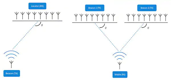
Figure 1: in the AOA direction finding method (left), the asset broadcasts its position (TX) to the AOA locator, which measures the angle of arrival of the signal. Using the AOD method (right), the beacon sends AOD information, while the mobile device receives (Rx) beacon signal and calculates the position. In each case, the receiving device needs computing power to calculate the direction of the departure aircraft.
The decision to include the direction search function in Bluetooth 5.1 is partly due to the influence of some enterprising companies, which have provided proprietary AOA and AOD solutions for Bluetooth low-power (ble) products. Bluetooth 5.1 makes it easier for developers to use the RF direction finding function by including updates to the core specifications, so as to extract "IQ" signal data (in-phase and quadrature phase information) from ble packets more easily. This, in turn, makes it easier for developers to implement location service applications.
For example, the AOA method is suitable for tracking and transmitting ble transceivers. The transceiver uses a single antenna to send packets with direction detection enabled, which are received by a multi antenna "locator". The locator samples IQ data from the signal packet when switching between each active antenna in the array. By doing so, it detects the phase difference of the signal due to the difference in the distance from each antenna in the array to a single transmitting antenna. Then, the positioning engine uses the phase difference information to determine the angle of the received signal, thereby determining the direction of the transmitter (Fig. 2).
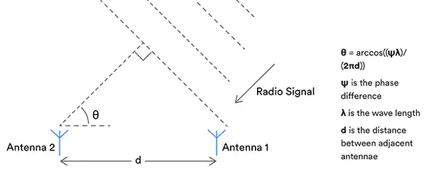
Figure 2: if the signal phase of each antenna is known( θ), Wavelength( λ) The arrival angle of the radio signal can be calculated based on the distance (d) between the antenna and the adjacent antenna.
Combined with the calculated signal direction from two or more locators, the transmitter can be accurately located (Fig. 3).
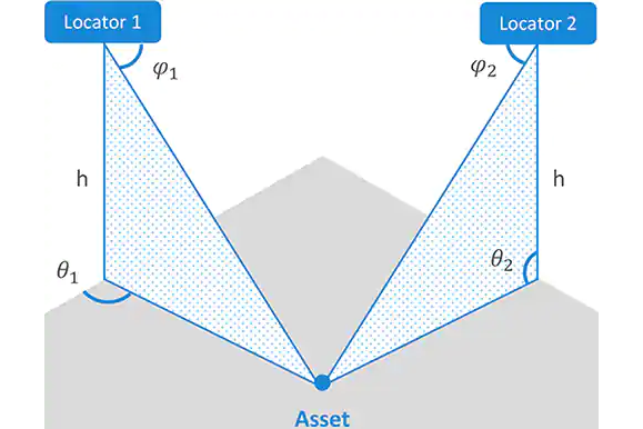
Figure 3: by calculating the AOA of signals at two fixed locators, the position of transmission assets in three dimensions can be calculated. If you know the absolute coordinates of the locator, you can also calculate the absolute coordinates of the transmitted asset.
(Figure 4). For the AOD method, the opposite is true. In this case, a device with an antenna array sends a signal through each of its antennas. When each signal packet from the antenna in the array reaches a single antenna of the receiver, it is phase shifted from the previous signal due to its different distance from the transmitter (Fig. 4).
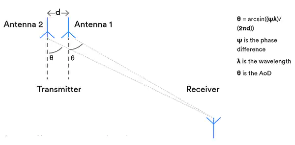
Fig. 4: when using the AOD method, when each signal packet from the antenna in the array reaches a single antenna of the receiver, it is phase shifted from the previous signal due to the different distance between it and the transmitter.
(Figure 5) the antenna of the receiving device extracts IQ samples from the signal packet and forwards them to the positioning engine, which then uses the data to determine the angle of the received signal, so as to determine the direction of the transmitter. The system is suitable for applications such as indoor navigation, in which the transmitter is a fixed reference point and the receiver is, for example, a consumer's smartphone.
Bluetooth 5.1 update
Bluetooth 5.1 requires changes to the RF software protocol (or "stack") and, depending on the chip manufacturer, some enhancements to the hardware (radio). First, the revised protocol adds continuous tone extension (CTE) to any Bluetooth packet used for orientation. (otherwise, the packet will remain unchanged, so it can be used for standard ble communication.)
CTE is a pure (i.e., unmodulated) tone transmitted at Bluetooth carrier frequency plus 250 kHz (or sometimes 500 kHz when using ble's higher throughput mode) for 16 to 160 microseconds (µ s). The tone is composed of "no white" sequence of "1", and the transmission time is long enough so that the receiver can extract IQ data without modulation interference. Since the CTE signal is sent last, the cyclic redundancy check (CRC) of the data packet is not affected.
The second important addition to the specification is to make it easier for developers to configure protocols to perform IQ sampling. This configuration includes setting sampling timing and antenna switching, which is very important for the accuracy of position estimation.
Although various IQ sampling timing configurations can be adopted, IQ sampling is usually recorded every 1 or 2 µ s in the reference period of each antenna, and the results are recorded in the random access memory (RAM) of ble SOC. Shows how the phase of the received signal varies with the sampling of different antennas in the array (Fig. 5).

Figure 5: signals from a single transmitter exhibit different phases when reaching antennas at different distances from the source
Recording IQ samples is only the first step in building a location service application. In order to complete the task, developers must design or select the best antenna array for the locators and beacons used in the application, and master the complex algorithms required to perform DF calculation.
Calculate signal direction
Antenna arrays for DF are usually divided into three types: uniform linear array (ULA), uniform rectangular array (URA) and uniform circular array (UCA). As the name suggests, linear arrays are one-dimensional, while rectangular and circular arrays are two-dimensional. Ula is the easiest to design and implement, but its disadvantage is that the azimuth can only be calculated by assuming that the tracked equipment is always moving in the same plane. If this is not the case, the accuracy will be affected. URA and UCA can reliably measure azimuth and elevation
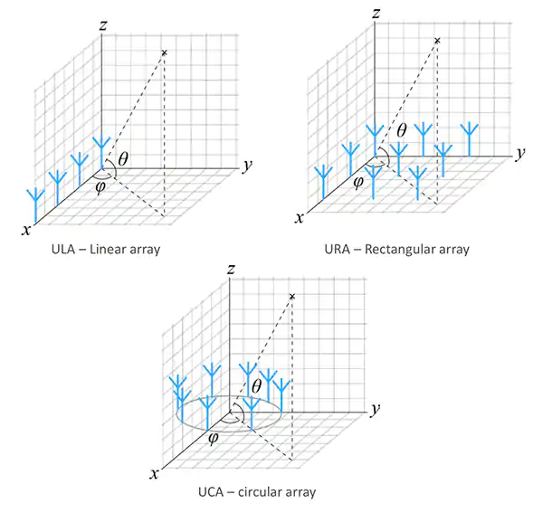
Figure 6: AOA and AOD direction finding technology requires antenna array, and its common forms include linear, rectangular and circular. Although each type of array can obtain information about elevation and azimuth, rectangular and circular types can provide more reliable azimuth data.
Designing antenna arrays for direction finding is not easy. For example, when antennas are arranged in an array, they interfere with each other's response by coupling with each other. To address this impact, estimation algorithms usually require predefined array responses. For example, a popular commercial algorithm mathematically assumes that the array consists of two identical subarrays. Fortunately, for those who lack antenna expertise, commercial antenna array products with defined characteristics can be used.
An effective antenna array will ensure that accurate IQ samples are collected. However, the raw data is not enough to determine the signal direction. Data must be processed to take into account multipath reception, signal polarization and propagation delay, noise and jitter.
Since RF direction finding is not a new subject, there are several mature mathematical techniques to estimate the angle of arrival based on IQ samples obtained in practical applications. The definition of the problem is very simple, that is, to estimate the angle of arrival of the transmitted (narrowband) signal to the receiving array (the calculation of departure angle is similar). Less mathematical operations are needed to solve this problem.
In basic terms, given the IQ sample data set of each antenna in the array, the commercial algorithm first calculates the data vector "X" (and assumes that the signal is a phase shifted and scaled sinusoidal (narrowband) signal) according to the following formula:
Equation 1
Where "a" is the mathematical model of the antenna array ("steering vector"),
"S" is the input signal and "n" is the noise term.
Then, using X, the IQ sample covariance matrix "RXX" is generated using the following formula:
Equation 2
This sample covariance matrix is then used as input to the main estimator algorithm. One of the most popular and mature algorithms for frequency estimation and radio direction finding is multiple signal classification (Music). In technical terms, music uses eigenvector decomposition and eigenvalues of the covariance matrix to estimate AOA based on the properties of the signal and noise subspace.
The formula used is:
Equation 3
Where "a" is a diagonal matrix containing eigenvalues and "V" is a matrix containing corresponding eigenvectors.
Once V is isolated, it can be used in the formula for generating pseudo spectrum. The peak of the spectrum appears at the angle of arrival of the received signal (formula 4):
Equation 4
The final spectrum takes the form shown, and the peak appears in the direction of arrival of the transmission signal (Fig. 7).
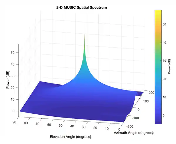
Figure 7: the music algorithm uses IQ samples to generate a success rate pseudo spectrum with a peak that identifies the location of the transmitting device. The example shows a two-dimensional pseudo spectrum in which the transmitting device is located at an azimuth of 50 degrees and an elevation of 45 degrees. (image source: silicon labs)
Running direction finding algorithms is computationally intensive and demands plenty of RAM and Flash memory capacity. The running direction finding algorithm requires a lot of computation and a lot of ram and flash memory capacity.
If you have any questions, please contact us by the following ways